
To meet the zero global zero flaring initiative by 2030, we provide different gas flaring recovery strategies to meet the global commitment. These strategies will be discussed below in details.
In industrial facilities, the flare gas recovery system is designed to collect the routine gas flaring from the flare header before reaching the flare stack and recycle it back to the process plants. Flare gas recovery can be accomplished through the following options:
- Flowback flared gas to existing low pressure compressors
- Installing of flare gas recovery systems
- Load reduction credits
- Minimize the flared, purged and leaked gas
After exercising all options of eliminating and reducing the flared gas, the FGRS can be utilized to capture the purge gas and recycle it back. FGRS is an essential element of any strategy to achieve zero flaring. Flare gas recovery can be achieved by using any of the following options:
- Flowback to existing atmospheric compressors.
Flowback can be achieved when operating the flare header at higher pressure than the lowest operating pressure in the plant. For example, flowback was achieved in one of the facilities by installing a water seal drum and increasing the operating pressure of the flare header to above 2 psig while operating the atmospheric compressor at 0.7 psig. This option capitalizes on the existing need of atmospheric pressure gas compression in the oil and gas facility.
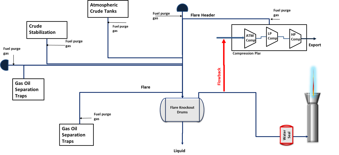
Figure 8: Flare system with flowback as FGRS
- Compressor based flare gas recovery system (CB-FGRS).
A conventional FGRS using gas compressors is the normal choice deployed in many facilities to recover the routine gas flaring but it was found to have high CAPEX and OPEX (maintenance, high power consumption and labor intensive) compared to the value of the recovered gas. Also, the compressors based FGRS is more complex and less reliable than the ejector (static) based FGRS. A compressor based flare gas recovery system is the least favored choice compared to flowback or ejector based flare gas recovery system.
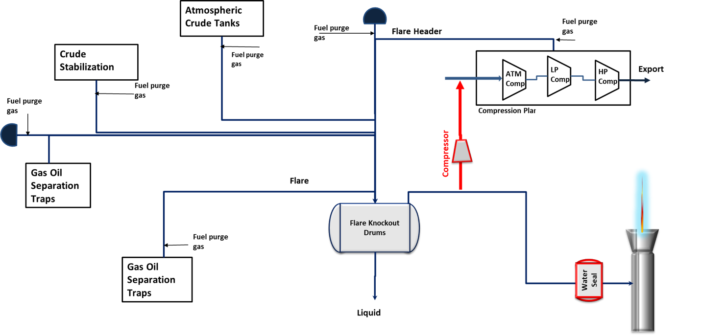
Figure 10: Flare system with compressor based FGRS
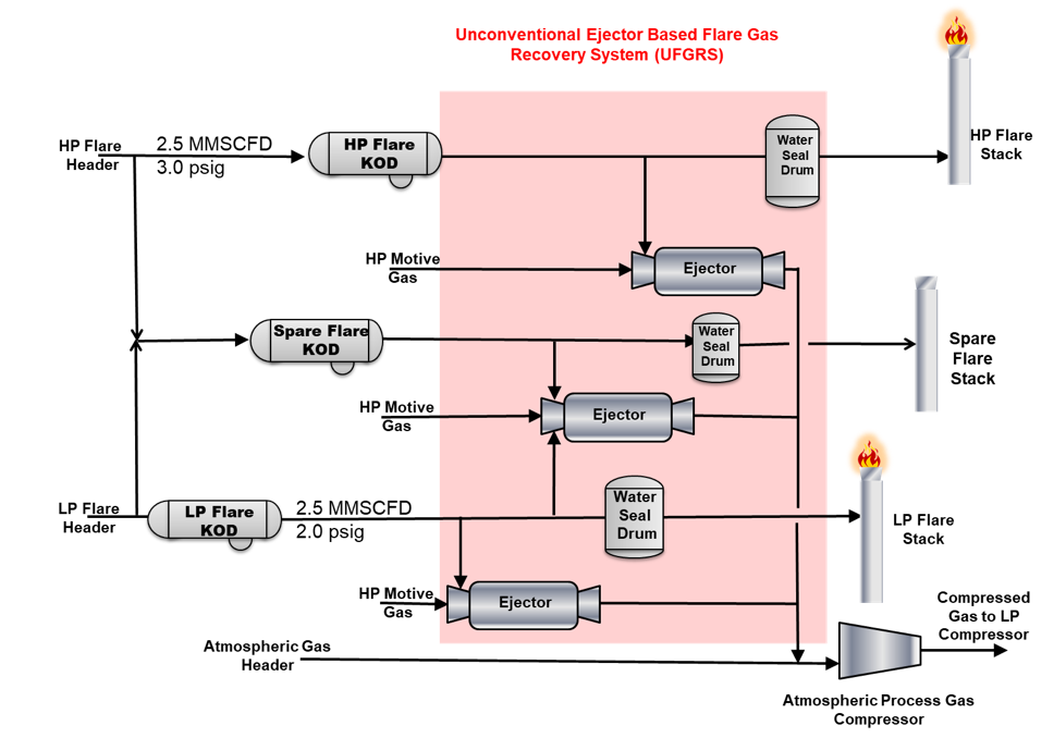
- Ejector Based Flare Gas Recovery.
When there is no atmospheric pressure compressor or blower installed, ejector-based flare gas recovery system can be utilized using gas or liquid as motive fluid depending on the availability.
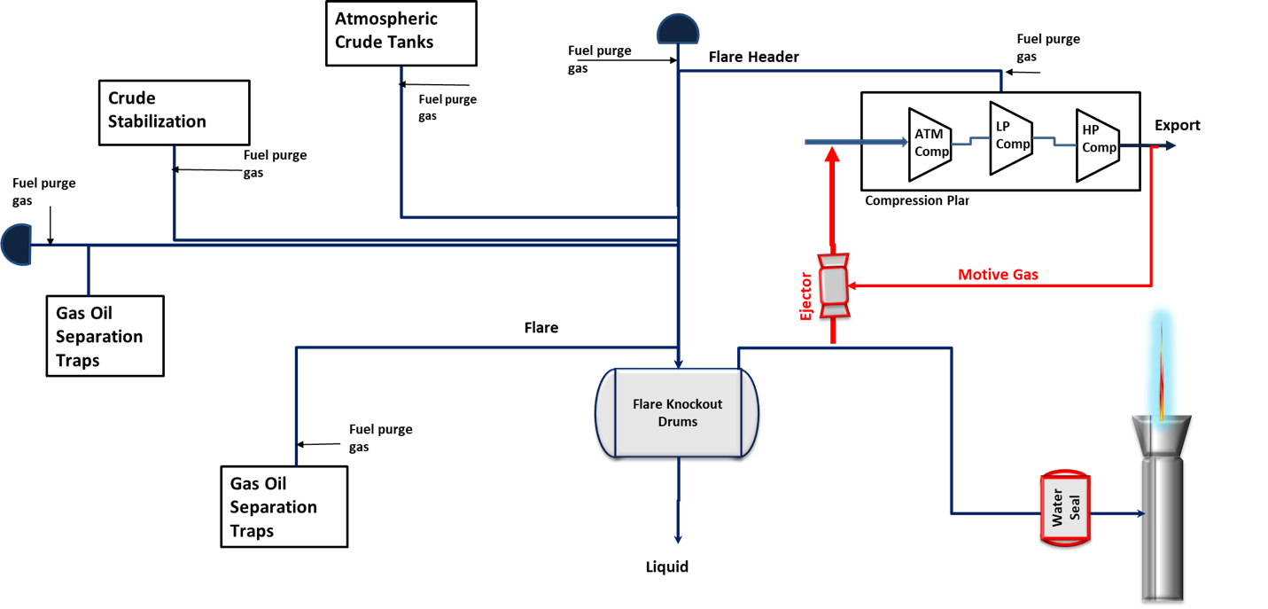
Figure 9: Flare system with ejector based FGRS
Case Study:
Plant-N uses more than 1.825 billion standard cubic feet per year (1.825 BSCFY) of gas as purge gas (routine flaring) to maintain the integrity of the massive flaring network. While flaring of such a large amount of gas results in accrued emissions and loss of associated energy, it also carries a potential risk of release of high H2S gas in case of flare tip flameout. Therefore reducing, recovering and reusing the routine flaring gas will have great impact on improving the personnel safety, increase energy recovery and reduce environmental pollution. A conventional FGRS using compressors was found to have CAPEX, maintenance and power consumption higher than the value of the recovered gas in most cases. As a result of the latest stringent corporate regulation to cut carbon emission, the team decided to recover more the 100% of the flared gas using the new patented ejector based static FGRS.
The objective is to eliminate the high H2S hydrocarbon gas release to atmosphere for any upset flameout scenario from GOSP-N massive flare and relief system and continuously recover 1.825 billion standard cubic feet per year (1.825 BSCFY) of valuable purge gas. Also, to recover the flare with the lowest CAPEX and OPEX. The implemented schematic of the ejector based FGRS is shown below.
Achieved Benefits:
- Continuously recover 1.825 billion standard cubic feet per year o fared gas.
- Reduce carbon emissions as a result of minimizing, recovering and reusing the flared gas instead of burning it.
- Low operating and capital cost compared with the compressor based FGRS.
- Less labor intensive and more reliable than the compressor based FGRS.
- Environmental protection and avoid the release of toxic gas to the atmosphere during flameout.
- No gas compressor required in the proposed FGR schemes, thereby reducing associated installation and operation costs.
- Enables operating existing atmospheric compressors and low pressure compressors at higher capacity thereby minimizing energy wastage associated with anti-surge recycling and also improving reliability of the compressor.
- Enhance Oil Recovery:
For the small and remote facilities where the gas is not feasible to transport it to the end user, the flared gas can be recovered and utilized for enhanced oil recovery. This approach has double the benefits of minimizing the environmental pollution as well as enhancing the oil recovery.
Case Study:
One of the remote GOSPs produces more than 1600 MMSCFD of associated gas. Additional gas facility was installed to recover the NGL from the gas and reuse the excess gas for enhanced oil recovery. The gas will be flared and wasted if it was not reused for enhanced oil recovery.

- Stripping Gas
Separated gas from high pressure drums can be recovered and utilized as stripping gas for nearby liquid strippers for enhanced separation or in the reboilers as fuel gas.
Case Study: Flash gas separated from triethylene glycol flash drum is separated and sent to the fuel gas drum to fuel gas knockout drum to separate any liquid as shown below. The separated gas is then used as fuel gas to the TEG reboiler or can be used as stripping in the surge tank to increase the glycol quality to beyond 99% at lower operating temperature.

Figure 11: Reuse of flash gas as stripping gas in the surge tank or as fuel gas in the reboiler
- Emergency Gas Flaring Recovery:
In addition, the innovative ejector based FGRS is capable of handling high turndown ratios compared to convention compressor based FGRS. Also, additional innovative parts of this idea is the integration with the existing compression system and the use of only static equipment like ejectors, pipes, valves and water seal drums to recover the waste/flare gas. The idea has very low operating cost compared to conventional flare gas recovery systems, apart from significant gas savings.
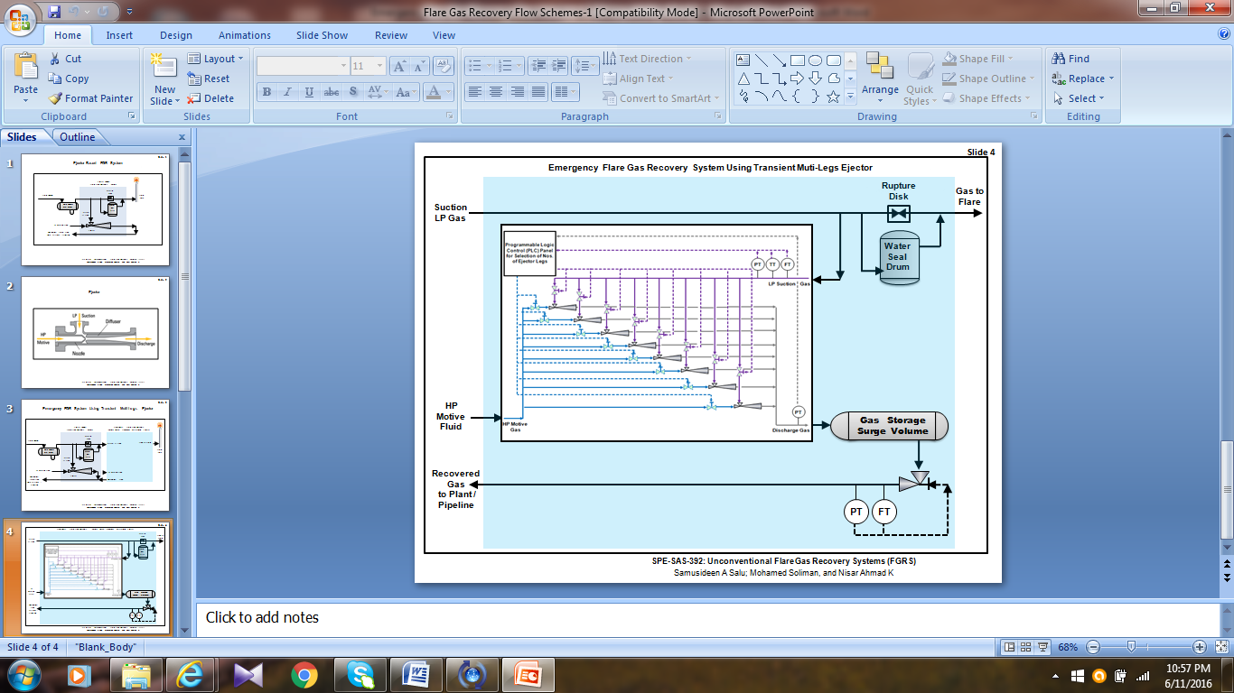
Figure 12: Patented Emergency Flare Gas Recovery System
To extend the scope of the flare gas recovery beyond the routine gas flaring, and to achieve total-zero flaring facilities, a technology or system capable of also recovering gas releases associated with non-routine flaring from emergency events, maintenance/operational activities, safety pressure relieves, etc., as in this invention, was developed and patented. The invented emergency FGRS will rely on a specially designed and configured “transient-multiple-legs” ejector, which will be capable of effectively collecting gas stream that are normally released during emergency depressurization scenarios from a process plant. The special ejector will be capable of recovering emergency gas releases and boosting its pressure to an intermediate discharge pressure by utilizing high-pressure motive fluid (gas, water or steam). The ejector will also be capable of discharging at a varying pressure to enable pressurization of a destination gas storage tank.
References
- https://pubdocs.worldbank.org/en/503141595343850009/WB-GGFR-Report-July2020.pdf
- Mohamed Ahmed Soliman, Variable Speed Pipeline Pig with internal Flow Cavity, US10,119,647 & 10,077,863 (2018)
- Mohamed Ahmed Soliman, Variable Speed Pipeline Pig with internal Flow Cavity, US9,810,365 (2017)
- M. Soliman. Adverse Effect of Oversizing Upstream Gas Oil Separation Plants on Energy Consumption, the International Petroleum Technology Conference, Beijing, China, March 2019
- Salu, Samusideen A., Soliman, Mohamed, and Nisar Ahmad Ansari. “Unconventional Flare Gas Recovery Systems (FGRS).” Paper presented at the SPE Saudi Arabia Section Technical Symposium and Exhibition, Al-Khobar, Saudi Arabia, April2014. doi: https://doi.org/10.2118/172240-MS
- Mohamed Ahmed Soliman; Samusideen A Salu; Abdullah Y Al-Aiderous; Nisar Ahmad Ansari; Khamis Al-Hajri; Ellyes Mecikar.” Unconventional Waste & Flare Gas Recovery System UFGRS in New Circular Economy”. Paper SPE-207956-MS presented at the Abu Dhabi International Petroleum Exhibition & Conference, Abu Dhabi, UAE, November 2021. https://doi.org/10.2118/207956-MS
- Dilip K. Das, Overpressure Protection of a Pressure Vessel By System Design through the Application of ASME VIII Ug-140 in Lieu of a Relief Device By an Appropriate Choice of Mawp and/or By Safety Instrumented System, AIChE Spring Meeting and Global Congress on Process Safety, April 2015, Austin,
- https://www.imi-critical.com/products/mechanical-hipps/
- https://instrumentationtools.com/overview-of-hipps-system/
- https://www.ge.com/news/reports/fire-power
- https://documents1.worldbank.org/curated/en/469561534950044964/pdf/GGFR-Technology-Overview-Utilization-of-Small-Scale-Associated-Gas.pdf