
To achieve the Zero Routine Flaring (ZRF) Initiative by 2030, here is the list of latest developed strategies to achieve this ambitious goal through Eliminate, Substitute, Reduce, and Recover strategies.
Zero Routine Flaring by 2030 Initiative
Launched in 2015, the ZRF Initiative commits governments and oil companies, to end routine flaring no later than 2030. Gas flaring is the 160-year-old industry practice of wastefully burning, rather than using or conserving, associated gas, a by-product of oil production. The flaring of gas contributes to climate change and impacts the environment through the emission of CO2, black carbon and other pollutants. It also wastes a valuable energy resource that could be used to advance the sustainable development of producing countries. The Initiative is designed to facilitate cooperation between all stakeholders so that solutions to ending routine gas flaring can be identified and implemented.
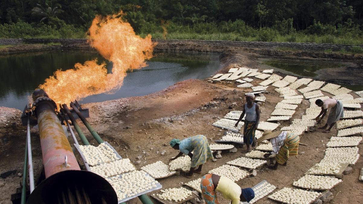
Figure 1 Courtesy of World Bank https://www.worldbank.org/en/programs/zero-routine-flaring-by-2030/about
Different Strategies towards the zero flaring initiatives are:
1. Eliminate Gas Flaring
Code Case 2211 of ASME Section VIII, Division 1 and 2 (UG-140):
The American Petroleum Institute (API) and American Society of Mechanical Engineers (ASME) provide criteria for the protection of pressure vessels and pipelines from excess pressure in any oil and gas facilities. Normally, the pressure safety relief valves are used as the main means of protection while the flare system is used to safely manage and combust the gases relieved during any overpressure scenarios. API 521 and Code Case 2211 of ASME Section VIII, Division 1 and 2 allow the use of an SIS in lieu of a pressure relief device as long as the SIS meets or exceeds the protection provided by the pressure relief device. Case 2211(UG-140) provides the circumstances under which the user can replace the traditional relief devices to protect a pressure vessel from overpressure either by an appropriate choice maximum allowable working pressure (MAWP) so that the unmitigated pressures from all credible scenarios are less than MAWP of the vessel or through a safety instrumented system or a combination of safety instrumented system and traditional relief devices. Overpressure protection by system design in lieu of a relief device is simpler and more economical than the conventional relief system. Elimination of relief valves and utilizing a high integrity pressure protection system (HIPPS) will have great impact on reducing the flare and relief system, and consequently emergency and routine flaring. Therefore, the best strategy to achieve zero flaring is to try to eliminate flaring from the first place by utilizing the CASE 2211 (UG-140) when and where applicable. The best example for elimination of the flaring is through the utilization of HIPPS in the gas production platforms. API-521 reported that HIPPS can be used to
a) Eliminate certain overpressure scenario.
b) Eliminate the need for a particular relief device.
c) Provide system overpressure protection where a relief device is ineffective.
d) Reduce the probability that several relief devices will have to operate simultaneously, thereby allowing for a reduction in the size of the disposal system.
e) Reduce the demand rate on a relief device consequently reducing the risk.
The HIPPS can be either an instrumented or mechanical system. The instrumented HIPPS is a safety instrumented system that is designed to prevent over pressurization of plant. HIPPS is designed and built in accordance with IEC 61508 and IEC 61511 standards. HIPPS closes the source of overpressure within the required timeframe and incorporates redundancy within the initiators (pressure sensors), logic solver, and final elements (shutdown valves) with at least the same reliability as a safety relief valve. HIPPS consists of three main components:
- Initiators (pressure sensors) to detect the high-pressure events.
- Logic solver to process the input from the pressure sensors to an output to the final element
- Final control elements to perform the corrective action in the field by bringing the process to a safe state. In case of a HIPPS, this means shutting off the source of overpressure. The final element consists of a valve, actuator and solenoids or simply shutting down the source of power.
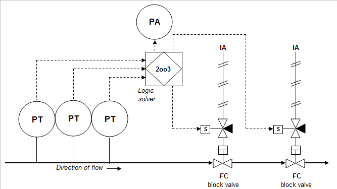
Figure 2: HIPPS System by Reptile209 – Own work, Public Domain, https://commons.wikimedia.org/w/index.php?curid=4754819
HIPPS Case Study:
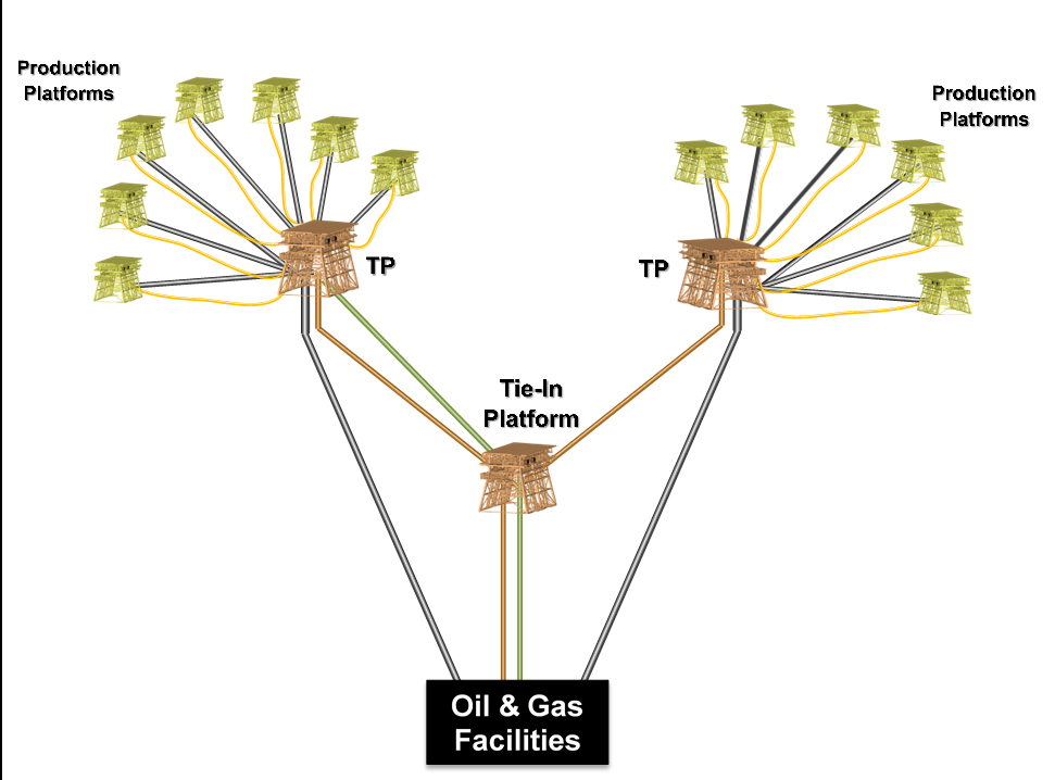
Figure 3: Offshore Oil & Gas Facilities
The Plant-A wellhead production platform (WHP) is a single super well with two identical production wing valves. The raw sour gas from the well is divided into two gas streams, called flow-arms. The design capacity of the well is 350 MMSCFD or 175 MMSCFD per flow-arm. Refer to the following simplified process flow diagram. Each flow-arm consists of mainly well production wing valve, choke valve, two (2) HIPS valves in series, and its associated pressure, temperature and flow transmitters. The production from each arm goes through a common header where the HIPS solid state logic solver monitors and senses the overpressure in 2 out of 3 (2oo3) voting configuration.

Figure 4: HIPPS installed at the wellhead
Mechanical HIPs
Mechanical HIPPS is a complete safety system that operates in applications without an electric power source. The technology comes in two variations: Self-actuated pneumatic, when instrument air/gas supply is available. Self-contained hydraulic, with locally installed oil tank and manual pump.
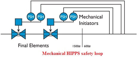
Figure 5: Mechanical HIPPS. Courtesy of instrumentationtools.com
2. Substitute Fuel Purge Gas with N2 or CO2:
One of the major sources of flared gas is the purge gas. Purge gas is used to prevent the O2 Ingress into the flare system. The main purpose of using the purge gas is:
- To prevent low flow flashback and avoid flame instability of the flare.
- To maintain positive pressure in the system, thereby preventing ingress of air that could cause a catastrophic explosion.
- To keep the flare headers and flare lines from sitting stagnant with corrosive (H2S) gas, purge gas is required to sweep the lines from all points at the far upstream ends and ensure that there is continuous constant flow in all lines at all times.
Substituting the purge gas with other inert gases like N2 or CO2 will have a direct impact on the flared gas. N2 can be used to substitute natural gas as purge gas and consequently does not require recovery. Using N2 will also provide positive environmental impact by eliminating routine gas flaring and reducing emissions of nitrogen oxides (NOX), volatile organic compounds (VOCs), and carbon dioxide (CO2). Further to the positive environmental impact, using N2 as purge gas will be cheaper and conserve the valuable natural resources.

Figure 6: Flare system with no flare gas recovery
Case Study:
- In one of ADNOC’s gas processing facilities, nitrogen was used to replace the fuel gas purge for four high-pressure flare systems to avoid burn-back. This was highly beneficial because it did not cause any detrimental effect to the tip and pilots. ADNOC claimed that the implementation of recommendations enhanced the reliability, availability and asset life of the safety critical flare system.
- In one of the GOSPs, the use of nitrogen to replace the purge gas was assessed and found feasible. A total of 540 MMSCF per year of valuable natural gas was replaced using nitrogen generated from N2 generation package. Using N2 as purge gas will not only conserve valuable gas product but it will also improve the reliability and life span of the flare tip and associated recurring maintenance costs of the flare tip
3. Reduce Flared Gas:
Purge gas reduction:
Going back to the basis of the use of purge gas to prevent the formation of flammable mixture in the flare system by avoiding oxygen ingress, flashback, and vacuum. The purge gas can be reduced by the following methodologies:
- Accurate measurements of flared, purged and leaked gas.
- Install water seal at the inlet of the flare stack to maintain positive pressure in the flare header and prevent oxygen ingress.
- Minimize the flared, purged and leaked gas.
- Load reduction credits: API-521 provides load reduction credit for some favorable instrumentation response to reduce the flare system. The load reduction credit includes HIPS, operator intervention, basic process control, etc. The load reduction credits will reduce the overall system size and consequently flaring loads.
- Perform a more rigorous evaluation to better estimate the relief load and/or duration (e.g., perform dynamic analysis).
- Modify operating conditions to reduce the sizing basis for the safety relief valve (e.g., reduce upstream pressure to reduce relief load).
- Redesign equipment (e.g., rerate the equipment at higher design pressure/MAWP, which results in installing smaller control valve size if control valve failure sets the sizing basis).
- Reroute the relief device effluent stream back into the process.
- Install a SIS or HIPS to reduce the likelihood of relief discharge.
4. Reduce Operation Upsets
Reducing the operation upsets will have great impact in reducing the flaring such as reducing the impact of pipeline scraping on plant operation. For example, adopting new technologies such as the mechanically propelled variable speed scrapers Patent# US10119647 granted from USPTO (Soliman, 2018) can be utilized to minimize liquid slugs in the pipeline and flaring. This new scraping technology can be used to conduct routine and potentially intelligent scraping with minimum production loss. It will solve the bottlenecks of existing conventional scrapers/pigs, which require reducing the flow to meet the scraping velocity. It will also help to minimize the scraper getting stuck and reduce potential pipeline ruptures.

Figure 7: Variable Speed Pipeline Pig with internal Flow Cavity, Patent# US10,119,647 (Soliman 2018)
5. Improve Process Control Performance
Healthy process control layer will reduce the escalated high pressure events and consequently equipment trips and gas flaring. The basic process control system (BPCS) involves the whole control loop, which includes sensors, logic solvers and final control elements.
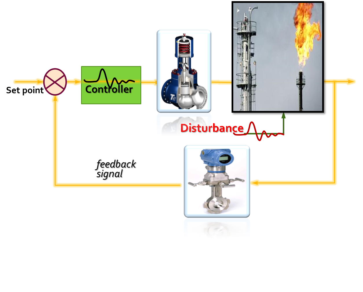
The process control can be enhanced by:
- Monitoring the performance of the full control loop
- Operating the controllers on Auto Mode
- Fine tuning of the controllers
- And finally, operation awareness and training
6. Recover Flared Gas
The flare gas recovery system is designed to collect the routine gas flaring from the flare header before reaching the flare stack and recycle it back to the process plants. Flare gas recovery can be accomplished through the following options:
- Flowback flared gas to existing low pressure compressors
- Installing of flare gas recovery systems
- Load reduction credits
- Minimize the flared, purged and leaked gas